Aerospace Fan Tester using a PLC and LabVIEW
Overview
Aerospace Fan Tester using a PLC and LabVIEW. An aerospace industrial fan manufacture needed custom LabVIEW software to control and monitor Modbus Data from a PLC (Programable logic controller). The software needed to monitor and control a user specified number of fans. Data acquired from the fans needed to be displayed to the user. Data collected from the fans needed to be logged to file for analysis.
Solution
We developed a custom LabVIEW program that communicated to Allen-Bradley Micro820 PLC's controlling the fans via Modbus. A programmable logic controller (PLC) or programmable controller is an industrial digital computer that has been ruggedized and adapted for the control of manufacturing processes, such as assembly lines, robotic devices, or any activity that requires high reliability, ease of programming, and process fault diagnosis. Modbus is a communication protocol that is used for transmitting information over serial lines between electronic devices.
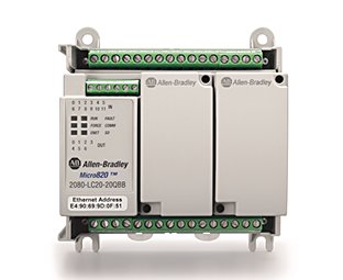
Allen-Bradley Micro820 PLC
The custom LabVIEW software needed to control and monitor a user specified number of fans. We created a modular architecture that allowed the user to specify how many fans needed to be tested. We created one fan process and then was able to run that process in multiple instances for each fan. This also allowed for easy maintenance since any change the to the individual fan process code applied to all configured fans.
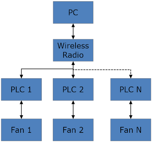
Block Diagram
Features
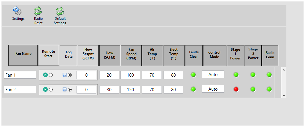
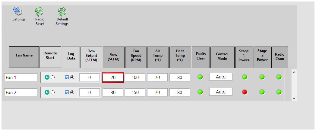
Main Screen
The main screen allowed the user to easily view the current status of all the fans under test. The user could toggle logging data for each individual fan. An alarm feature was developed. If the measured flow was outside a user specified limit the value flow value would be highlighted in red or yellow.
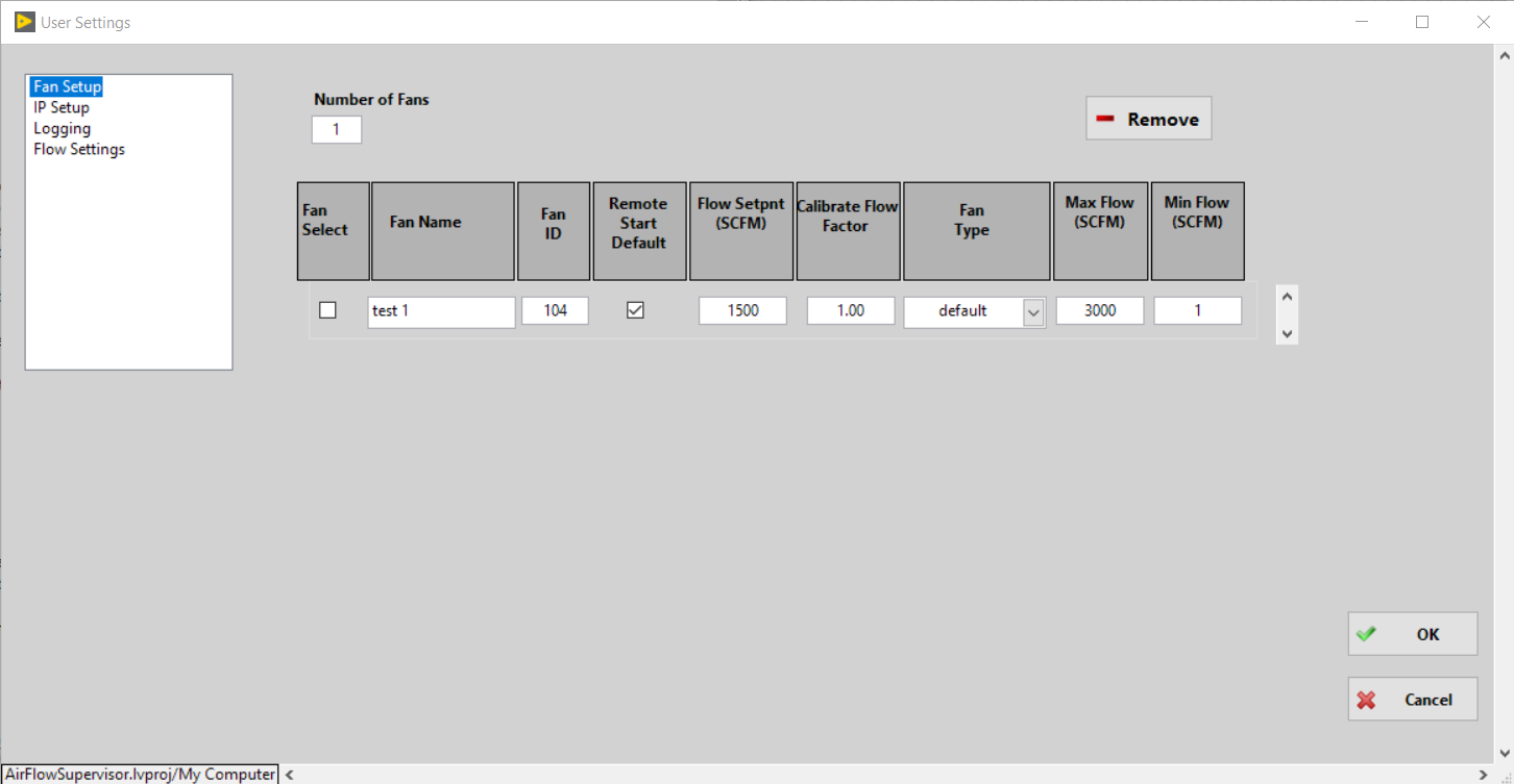
Setup Screen
The setup screen allowed the user to setup each fan. The user could specify how many fans to test and settings for each fan.
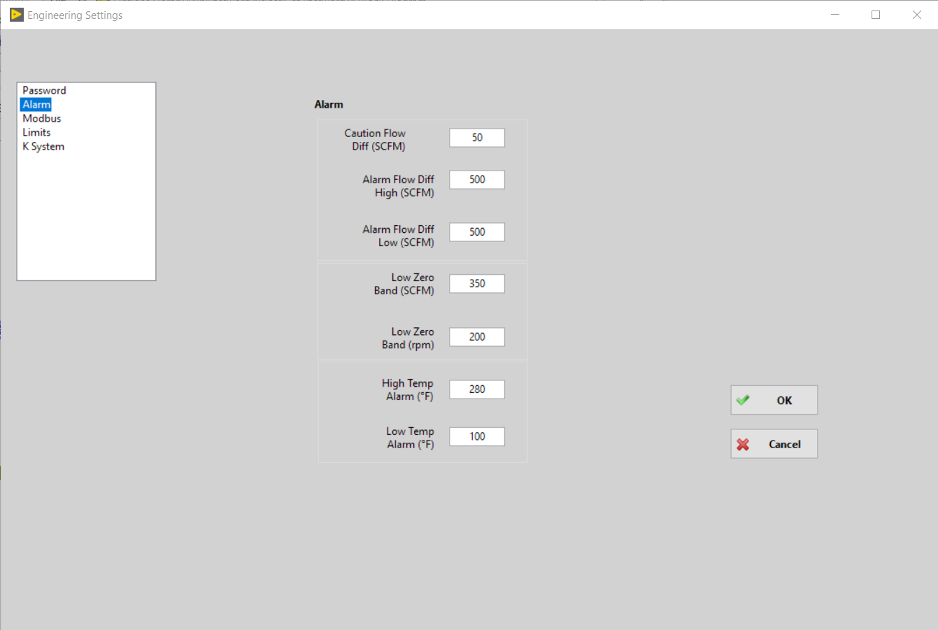
Engineering Settings
An engineering settings screen was developed to allow the engineer managing the software to set advanced settings. This dialog was password protected to prevent unauthorized access. This example of the engineering settings dialog shows how the engineer would set the alarm limits.
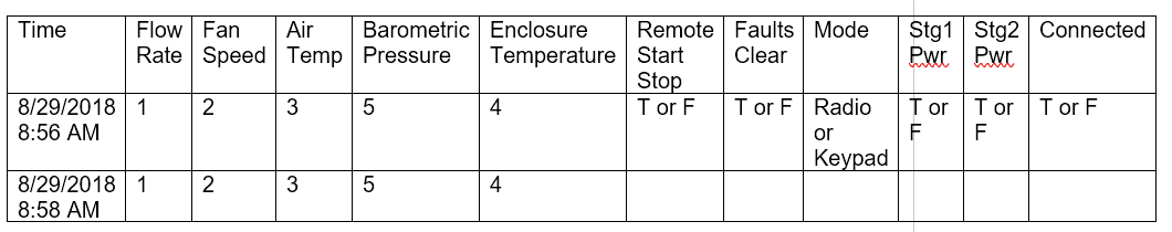
Data File
Data for each fan was saved as a CSV file. Comma separated value (csv) is a file format that is human readable and can be read by any analysis program i.e. Excel.
Result
The Aerospace Fan Tester using a PLC and LabVIEW allowed the customer to monitor and control the PLCs that were connected to the fans. The software was easy to use and the ability to simultaneously monitor a specified number of PLCs greatly improved the efficiency of the test. The modular architecture we developed improved the maintenance of the code because each instance of the fan was dynamically created by the software. This means that only one fan codebase needed to be maintained instead of a separate code base for each fan.
The customer was able to use existing PLC's and because LabVIEW has an extensive communication protocol library communicating with the PLC via Modbus was possible. This saved the customer from buying new hardware saving them a considerable amount of money.
Let's build an application together. Contact us today
- Learn how we do a project
- Learn about Micro820 PLC
- Learn about Modbus
- Learn more about LabVIEW
- Learn about other test systems we have done for Aerospace and Defense Customers