Data Acquisition Controller using CompactDAQ and LabVIEW
Overview
Data Acquisition Controller using CompactDAQ and LabVIEW. An automotive test lab needed a custom program that monitored temperature, pressure, voltage and controlled a digital output sequencer. They needed a simple intuitive user interface to reduce operator training costs. The user also needed the ability to specify limits on the measured channels. If a measured value exceeded the limit the software would stop the digital sequence. The software also needed to control a heater using a digital output.
The customer wanted to use off the shelf data acquisition hardware to reduce costs and standardize the hardware in the lab. The hardware also needed to be able to measure different signal types i.e. thermocouples, pressure sensors, and voltages.
Solution
We developed a custom LabVIEW application that interfaced with NI CompactDAQ hardware that monitored user defined analog inputs and digital inputs and outputs. A CompactDAQ system has a chassis that is connected to a PC through USB or Ethernet, and then populated with one or more conditioned I/O modules that provide direct sensor connectivity.
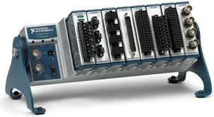
Example of CompactDAQ Hardware
The software easily allowed the user to monitor and log the measured data to file. The data was saved to a human readable csv file. CSV files can be read by any data analysis package i.e. Excel.
Dat
The software also allowed the user to create sequences of digital outputs. The user could define a step time when certain digital outputs were on or off. The user was also able to create a group of sequences so multiple cycles of groups could be run.
A temperature control routine was developed to control a heater via a digital output. The temperature control routine was developed in a separate thread so it would not interfere with the operation of the rest of the program.
The user had the ability to define limits on each of the analog inputs. When a measured value fell above or below the specified limit the sequencer would stop.
Features
Main Screen
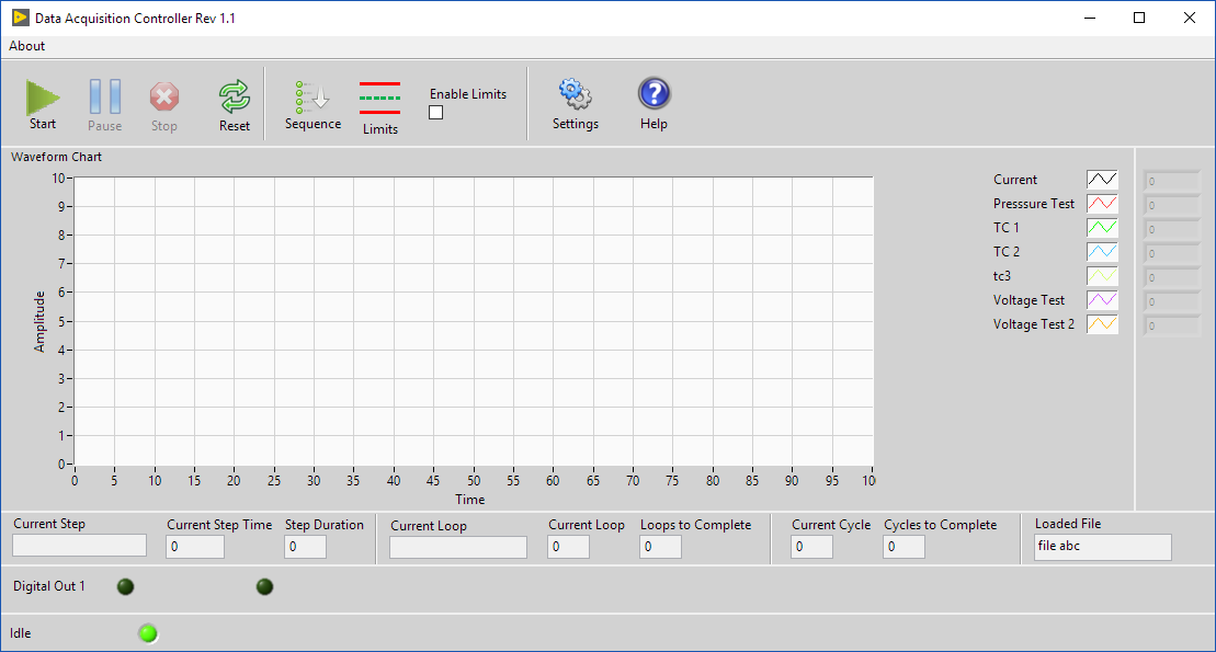
The main screen allowed the user to view the current measured values with respect to time. Controls were also available to start, pause, and stop acquiring and sequencing. The user could navigate to all the sequence, limits, and settings dialogs. Indicators were developed to show where the software was in the sequence and what the current values of the digital outputs were.
DatMain Screen of Data Acquisition Controller Software
Setup Dialog
This is the dialog screen that allows the user to set up the software. From the setup dialog the user could specify the test options and all the hardware channel address and properties. We used an object oriented approach that allows us to add or remove groups of options easily if the software needed to expand.
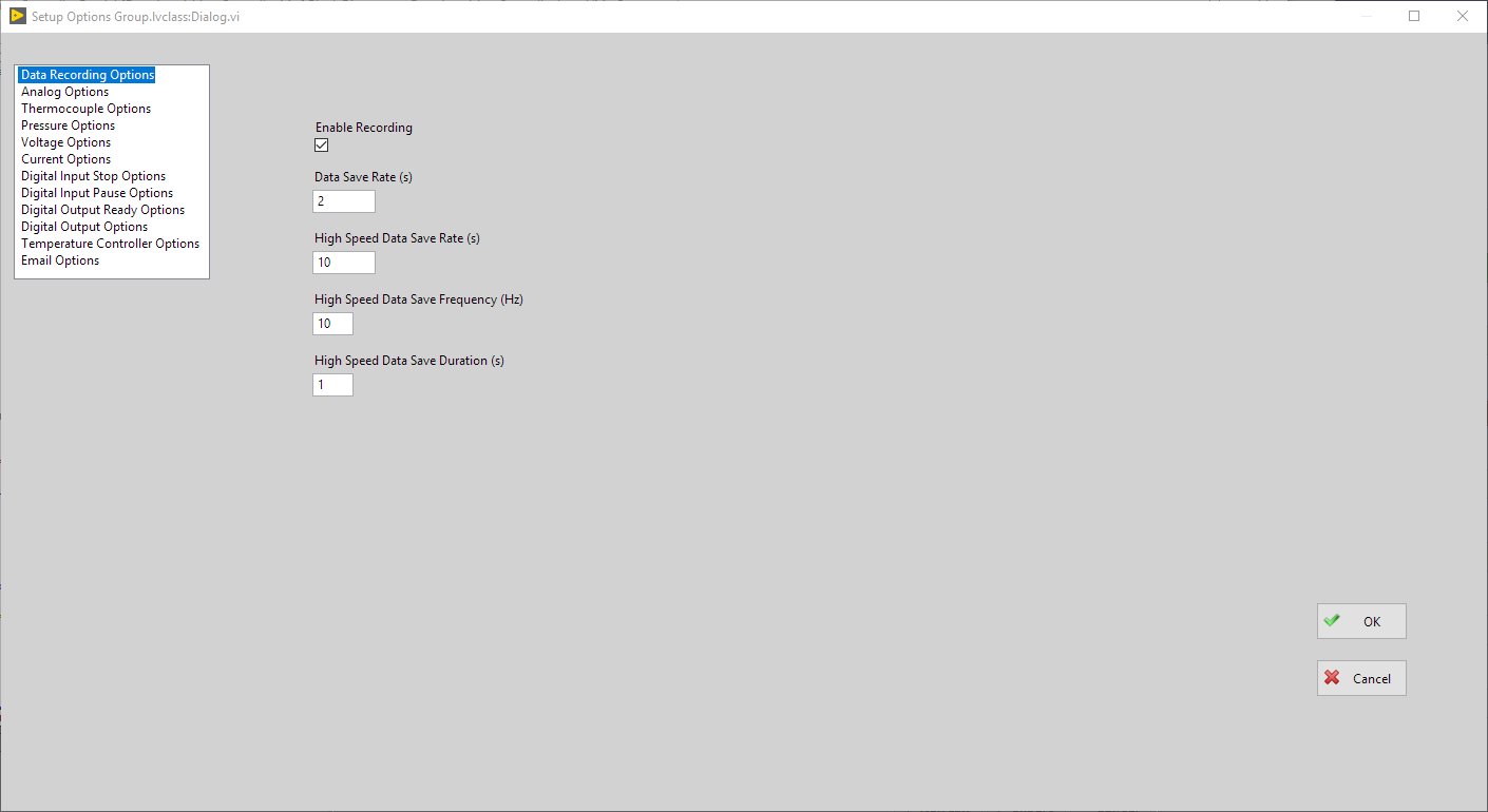
Setup Dialog
Hardware Setup
Shown here is how the user can set up Voltage channels. The user can set the channel name, physical hardware address, if the channel is enabled, and minimum and maximum values of the hardware inputs.
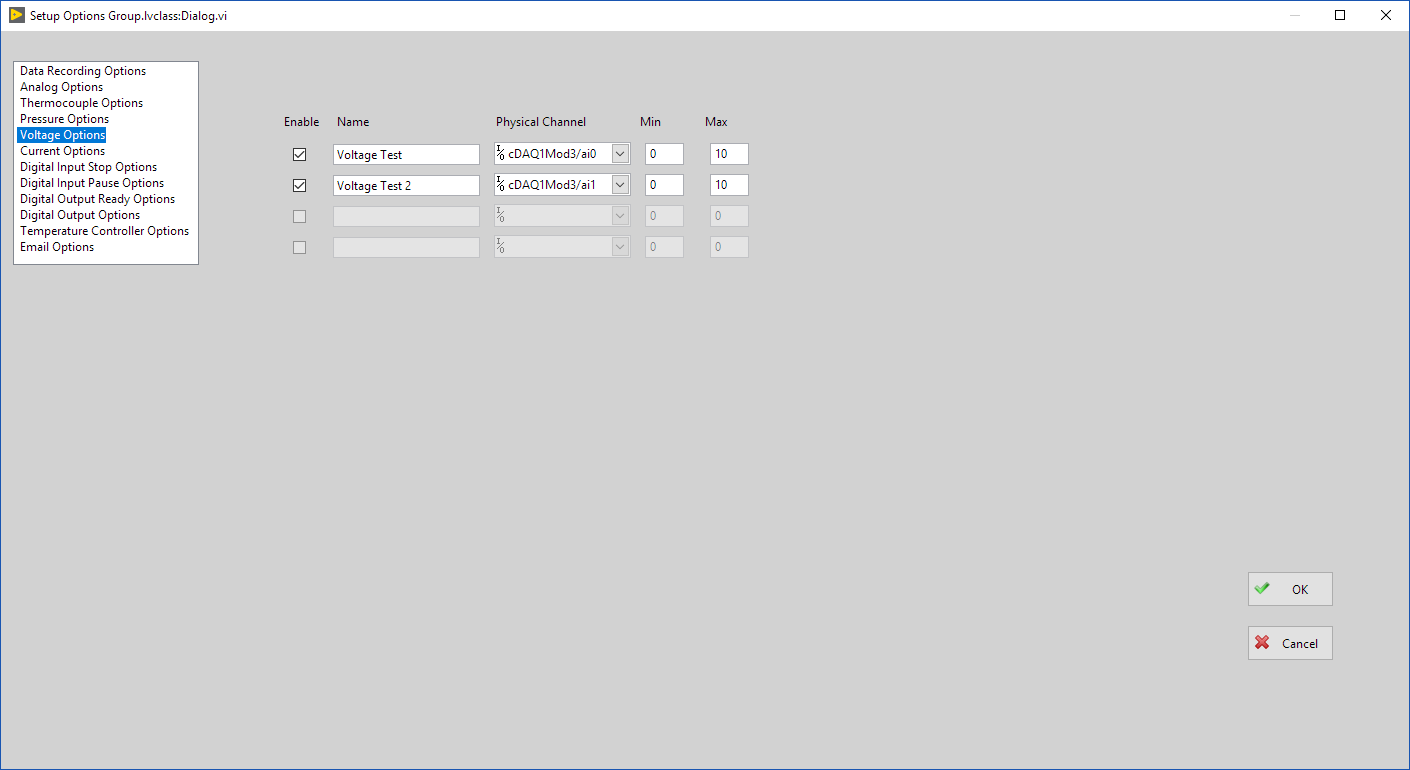
Voltage Setup
Sequencer Editor
The sequencer editor controlled the digital outputs. We defined a sequence as a Cycle, Loop, and Step.
The step was the amount of time the digital outputs were on or off. The editor would automatically load all the digital outputs configured from the setup dialog. The user then entered the step time and the state of each digital output. We added the ability to easily add or remove selected steps.
The loop was a group of steps. The user could name the loop and select how many loops to run. We added the ability to easily add or remove selected loops.
The cycle was the group of loops. The user had the ability to specify the amount of cycles to run.
We developed a feature to save and load configured sequences. This allowed the user to create a library of sequences to use on tests in the future.
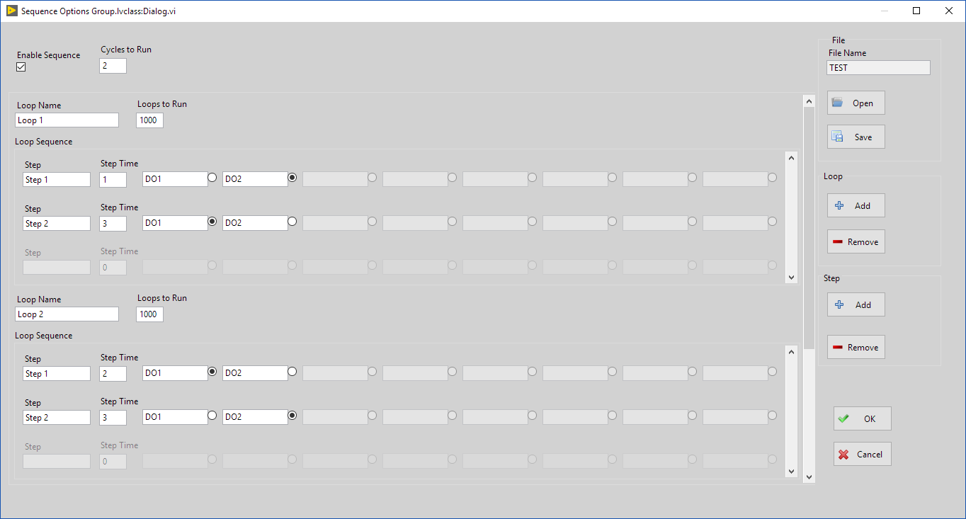
Sequencer Editor Dialog
Limit Dialog
The Limit Dialog allows the user to set limits on Analog Inputs. The channel names are automatically populated from the channel names specified in the setup dialog. The user can set minimum and maximum limits on the channel. If a limit is exceeded the acquisition and digital output sequence would stop and report an error.
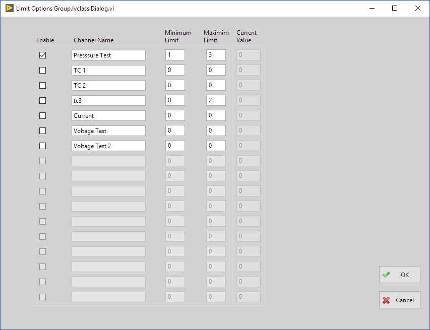
Limit Dialog
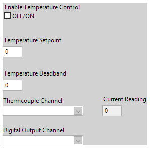
Temperature Controller
The temperature controller allowed the user to control a heater via a digital output. The controller would turn on digital output if measured temperature is below setpoint. The controller would turn off digital output if measured temperature is above setpoint plus deadband. We developed the temperature controller to be in a separate thread. This meant the temperature controller portion of the code ran independently of the rest of the program.
Result
Data Acquisition Controller using CompactDAQ and LabVIEW allowed the customer to easily measure and control the test they were running. The user interface was easy and intuitive to use requiring minimal operator training. The code was modular and written to current LabVIEW coding guidelines allowing future feature additions possible. Using the software the customer was able to automatically perform their test instead of manually running the test. This freed up technician resources saving the company time and money.
Let's build an application together. Contact us today
- Learn how we do a project
- Lean about PC based data acquisition
- Learn more about CompactDAQ
- Learn more about LabVIEW
- Learn about other test systems we have done for automotive customers